This is the forum archive of Homey. For more information about Homey, visit the Official Homey website.
The Homey Community has been moved to https://community.athom.com.
This forum is now read-only for archive purposes.
The Homey Community has been moved to https://community.athom.com.
This forum is now read-only for archive purposes.
Comments
I'm seeing the same thing but my housing seems to be machined in order to open up 'windows' for the IR leds, I see this on several IR emitters:
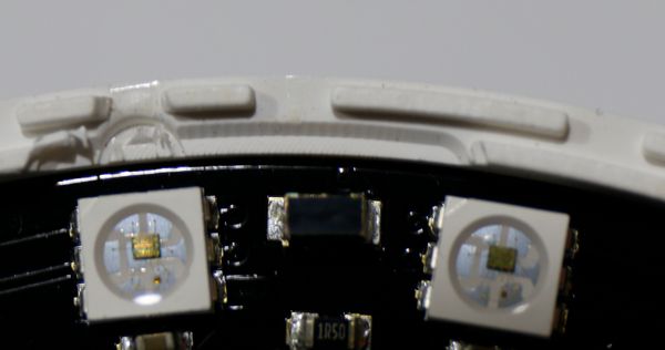
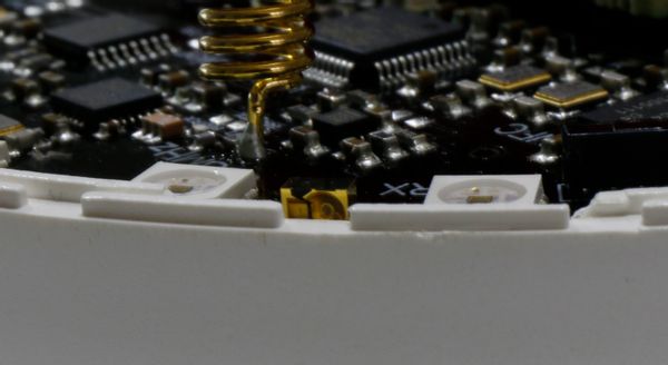
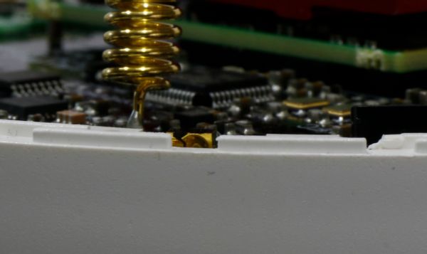
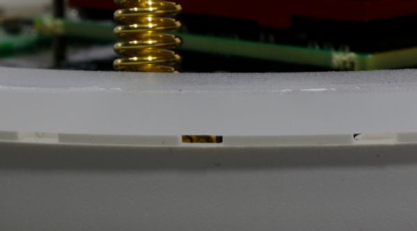
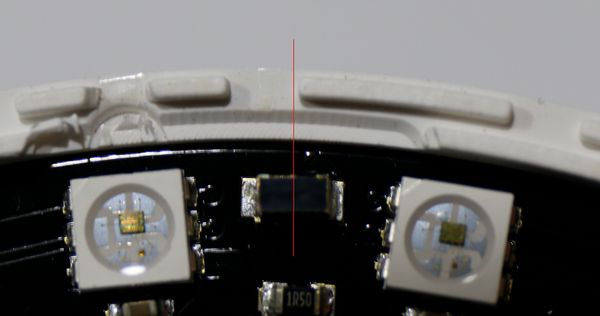
I also think the IR emitters (or PCB) are placed to low, in order to see the middle of an emitter you have to have an slightly elevated angle:
When you're only seeing half of the emitter it looks like this, note that it's still elevated form the horizontal plane:
And with the led ring on like this:
I'm not sure what the angle of the beam is, but the hole to send the signal trough is not really good aligned:
@MarcoF I think that if you find the datasheet of the LED's I think you van measure the distance from the emitter to the edge on the above picture.
Whoops... these pictures hurt my eyes....
Thanks for these great pics!
Could the fact of machined holes explain why some of my IR-holes are partly closed???
The industry standard is the ~940nm. The forums also suggest that Logitech uses that band too. (But who knows it happened before that Athom went with a wrong frequency)
Wikipedia: "Infrared wavelength: around 870 nm and 930–950 nm. Latter is preferred because water in atmosphere blocks sunlight in this wavelength making devices less susceptible to blinding."
I will focus on the right side, since that looks much easier to interpret:
The horizontal axis is the degrees of something (I'd assume the angle).
The vertical axis is the relative intensity (so a sort of efficiency, at which 1 is max efficiency).
Thus, it appears that efficiency is basically max at 5 degrees, and falls of very quickly (50% efficiency at 10 degrees, 10% efficiency at 20 degrees, no efficiency at 90 degrees).
Thanks and your explanation likes to make sense
So the left and right sides are "linked" like these colors? ;
Where green left of the middle is the max IR power between angle 0-5° and on the rights side power >80%+
Everything >5° results in a significant lower IR power.
So the IR-beam is at it max around a angle of 5° and outside the 0°-10° the beam <50%.
So the most important part is 0°- 5° where the beam is 80%+.
Regarding to @DaneeDeKruyff pictures, it looks like the 0-5° part of the beam is blocked by the housing. This because the leds center point is slightly below the edge of the housing.
The linear helps to get more accurate readings from the diagram.
The polar shows how it looks like in the real life. To illustrate it: lets imagine that it emits light in the visible spectrum than if you would place the chip next to the wall you would see that curve (roughly). The above polar diagram shows only half of the beam, it is rotationally symmetric.
Example:
I Agree!
But what happens if the holes are to high and/or holes are partly covered?
What will happen with the beam and IR power?
MarcelKuijper did that without success. Seems like the IR issue has many more layers.
I was also wondering why they use the same kind of chip as receiver? Surely you can use speakers and headphones as microphones but not the best way
You mean the IR receiver? There is a seperate IR receiver on the PCB.
It sits 'behind' the led ring and has no 'clear' line of sight. I have not seen any difference with or without the led ring. For me the receiving of signals heavily depends on the type of signal that is used.
When Homey is fully assembled it is able to pick up a Windows Media Center and Xbox 360 Remote (RC6 signal) even when I bounce it! But with others it doesn't recognise the signal even when pointed straight at the receiver with the top and ledring removed.
https://blog.athom.com/2016/04/17/a-technical-introduction-homey/#more-25
@Sommo No check page 1 for my test results.
@drlrcq i was able to put a Stanley knife between the top half and led ring couse of bad glue-ing.
According to ur fingernails u are not working in the IT business but ur very handy with the dremel, cool!
That short?
To be sure, this distance
You see 4 lines coming out of the IR-led;
The top and bottom are the 10° lines as specified in the datasheet.
The green line and red line are the 5° lines as specified in the datasheet.
In this situation the center of the IR-led is only 0.2mm below the hole of the housing.
The 2 lines in the center of the beam show the "5°" which is "narrowed" by the fact the LED is lower then the bottom of the hole.
Also did some calculations on the narrowed beam.
It seems that the narrow beam has, at 5 meter distance, a "surface" of only 23cm2 and is only 12cm high and 24cm wide.
This is corresponding to my test where I noticed that my IR-extender only shows a strong signal in a very small area by tilling Homey for a few millimeter and/or degrees.
This image shows that the 5° beam is very narrow and a large portion of the 10° beam is also gone.
In the image I didn't looked at whats happen if a IR-Led is place more left/right of the hole.
The image above shows that the IR-led is place more to the left of the hole and this will have the affect that also a large portion of the IR beam is block/gone.
Very curious to your thoughts and feedback
Thanks for making that drawing @marcof it gives a good insight on what part of the signal is lost due to the housing.
Maybe it's about time @emile or @stefan will comment on this...
Kudo's for all the effort you guys put in locating the problems, but the downpart is that it appears that for the current user really not that much can be done to improve it (other than attack your Homey with a Dremel...).